Although the installation of our amplification kits is rather simple, supported by our assistance and the manual always present in the box you receive, in case you are dealing with special installations (requiring more than one indoor antenna, due to the compliance of the building in which to amplify the mobile signal), it is essential to use tools that allow the transmission of the incoming mobile signal to multiple areas (to multiple indoor antennas), allowing an even distribution (in the case of splitters), or not (for couplers), of the output signal: we speak of signal splitters and couplers.
But when do we prefer to use a splitter and when a coupler? In this blog we will try to clarify the differences between these two components.
- Splitter: 4 different types for homogeneous signal distribution
- Couplers: An uneven signal distribution
1. Splitter: 4 different types for homogeneous signal distribution
When we talk about splitters, we are referring to devices that have the function of splitting the mobile signal received from the outdoor antenna, and amplified by the repeater, towards two or more indoor antennas, in a homogeneous way. This means that the output, the intensity of the output signal, with the same length of coaxial cable, will be the same on each indoor antenna.
A splitter allows you to connect multiple indoor antennas to a single repeater. The maximum number of connectable indoor antennas is determined according to the maximum coverage of the repeater.
We have 4 different types of signal splitters: 2-way splitter, 3-way splitter, 4-way splitter and 6-way splitter, each of which has different characteristics (and losses) from the others.
1.1 2 Way Splitter
It is the most common signal splitter for installations in private houses with a surface area of more than 300 m2 (and less than 700 m2) on two levels, or again, with particular structural characteristics.
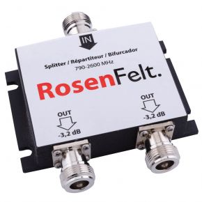
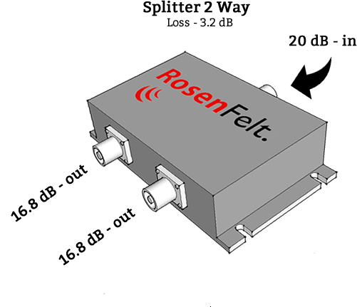
A 2-way splitter consists of two "outputs" and an "input": the input port, on one side, allows connection to the repeater/amplifier for signal reception; the two output ports, on the opposite side, are used for signal transmission towards the two indoor antennas (through two coaxial cables, one for the indoor antenna). There are therefore two indoor antennas that can be connected to this type of diverter.
In the case of a 2-way splitter, the loss generated by this signal deviation is equal to -3.2 dBm: this means that, if a repeater has a power of 13 dBm (the power of each repeater can be verified in the wording of the model, for example for the RF-EL13-H repeater, the signal strength will be 13 dBm), after passing through the splitter, the power will be reduced to 9.8 dBm, on each of the two indoor antennas.
1.2 3 Way Splitter
Here we are, another type of signal divider, the 3-way splitter. What will it ever mean? Nothing more than anything we've talked about so far regarding the 2-way splitter.
For this type of splitter, connection to three indoor antennas is required (possibly, for all splitters it is possible to use a dummy load in order to "plug" one of the outputs which would remain unused, thus avoiding total loss of the signal): it is necessary to account that, in normal conditions, each indoor antenna has a coverage of about 300 m2, therefore this type of splitter is used above all for areas between 700 and 900 m2 (or for buildings on three levels).
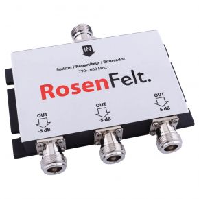
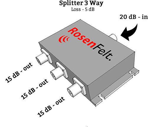
Here too, the composition is the same: on one side we find the input for connection to the repeater via coaxial cable, on the other side the three outputs for connections with the three indoor antennas.
In this case, the generated loss is equal to -5 dBm, on each of the indoor antennas.
1.3 4 Way Splitter
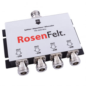
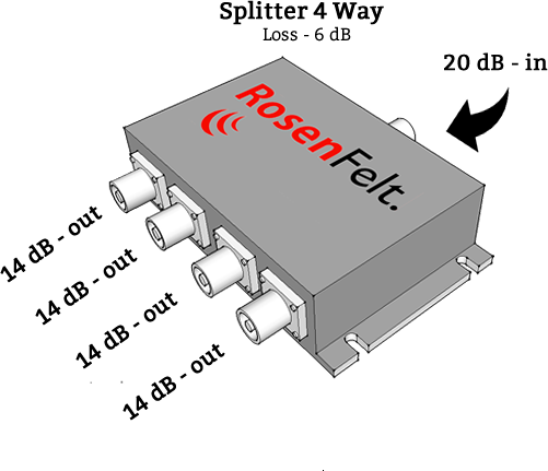
Third type of splitter, possibility of connection with a maximum of four indoor antennas: on one side we find the usual port for connection with the repeater, on the other the four outputs for connection with the four indoor antennas.
And the loss? In the case of a 4-way splitter, the loss generated on each of the indoor antennas is equal to -6 dBm. We therefore deduce that if you opt for this splitter, you will need to consider a fairly powerful repeater, such as the RF EL20-L model for example.
1.4 6 Way Splitter
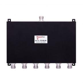
The last type of splitter we have is a less common splitter, usually used for large systems: the 6-way splitter allows connection with six internal antennas.
The loss of a 6-way splitter is -9.5dBm.
We find a signal input port from the repeater, six outputs on the other side for connection with the six indoor antennas.
2. Couplers: An uneven signal distribution
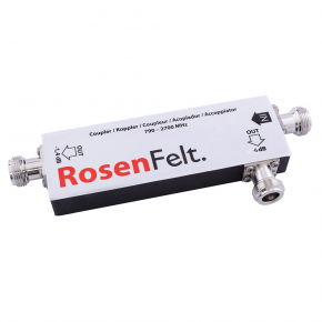
IThe second tool used for installations that require two indoor antennas is the coupler.
This accessory can be understood as a 2-way splitter, with the difference that the distribution of the input signal is not uniform:if the 2-way splitter allows the distribution of the signal towards two lines (indoor antennas) evenly, with a coupler you can distribute a stronger signal to a first output, and a weaker signal to a second output.
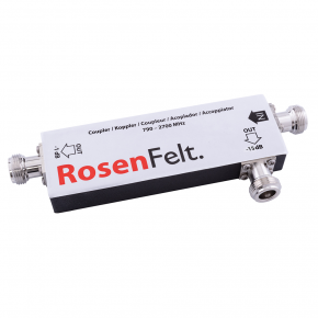
n our catalog you can find 6 different types of couplers: 5dB coupler, 6dB coupler, 7dB coupler, 8dB coupler, 10dB coupler and 15dB coupler.
2.1 Coupler 5 dB
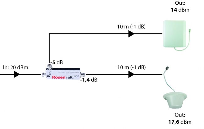
It is the most common type of coupler, the 5dB value indicates that the greatest loss, on one of the two outputs that will connect to the indoor antennas, is equal to 5 dB.
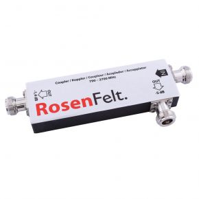
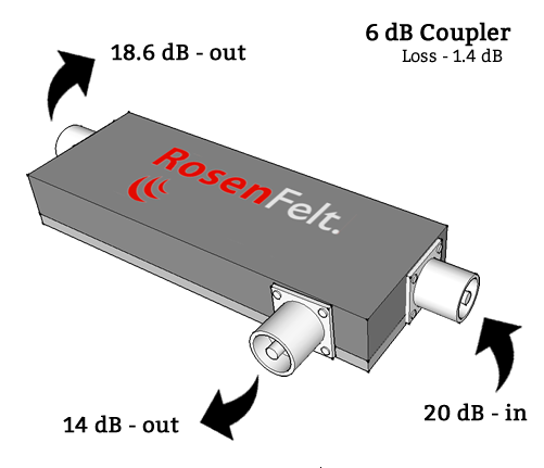
This explains how it works: the 5 dB coupler consists of three ports: on one side we find the input port, as for the splitters, for receiving the signal from the repeater, on the other side there are the two output ports of the mobile signal, which signal is distributed unevenly.
The first output "allows" a loss of 5 dB,the second output has a loss of 1,4 dB.
2.2 Coupler 6 dB
Second type of coupler, this time 6dB. As with the coupler described above, here too there is an uneven distribution of the signal: the 6 dB coupler has a loss of 6dB on the one hand, on the other hand the loss is still 1,4 dB.
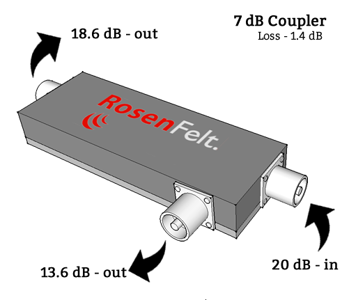
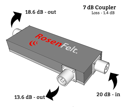
2.3 Coupler 7 dB
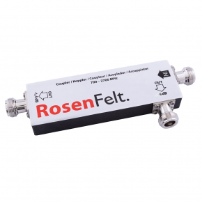
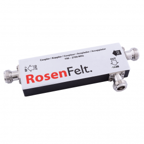
For the 7 dB coupler the greatest loss is 7 dB, for the other output the loss is still 1.4 dB.
The composition is always the same: on one side the input port for the connection with the repeater, on the other the two outputs for the connection (via coaxial cables) with the two indoor antennas.
2.4 Coupler 8 dB
As you will have well understood, the procedure for identifying the type of coupler and its losses is always the same.
What will happen if I install an 8 dB coupler? Exactly! We will have an output signal reduction of 8 dB for the first antenna, and, again, the same loss of 1.4 dB on the other.
2.5 Coupler 10 dB
We are referring to increasingly particular situations, to ever larger systems and buildings with ever greater square footage, as we proceed with the list of the different couplers.
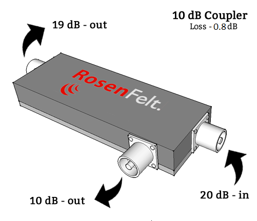
For installations that require two indoor antennas that are very distant from each other, the best choice might fall on an 10 dB coupler: 10 dB loss on one indoor antenna and...1.4 dB loss on the other? Not really. In this case the loss on the second output is smaller and is equal to 1 dB.
2.6 Coupler 15 dB
Here we are with the description of the last type of coupler, used in less common cases, the 15 dB coupler.
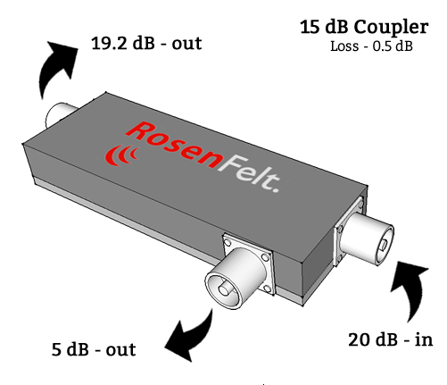
How does it work? Always the same concept accompanies its use, on one side we find the classic mobile signal input port, on the other side the two outputs. On the first output the loss is 15 dB, on the other, as for a 10dB coupler, it is 1 dB.
Now that we have clarified the concept and use of a coupler, you may be wondering why and when to use a coupler.
First of all, keep this concept in mind: to ensure satisfactory amplification of the mobile signal (maximum number of reception bars on your phone), the final signal output must be between 7 and 11/12 dBm.
Now let's try a practical example: let's imagine we want to amplify the 2G mobile voice signal and 4G LTE Internet for a building on two levels (ground floor and first floor): we have opted for the RF EL15-L; since the repeater is on the ground floor (with the 6 dBm coupler installed on it), we want to install the internal antenna on the ground floor at a distance of 10 meters from the repeater. We will use, for the connection with the coaxial cable and then with the internal antenna, the output which presents a greater loss, that of 6 dB and, including also the loss on the cable (there is a loss of 1 dBm for every 10 meters of coaxial cable) the total loss will be 7 dBm: therefore starting from the power of 15 dBm (RF EL15-L), subtracting the total loss of 7 dBm, the intensity of the output signal on the first internal antenna (output) will be by 8 dBm.
On the first floor, you want to install the second internal antenna at a distance of 40 meters from the repeater, which is located on the ground floor (for example, you want to install the internal antenna at the end of the corridor, because there are offices, laboratories, production activities, etc. and the mobile signal is absent): as mentioned, on the second output the loss for a 6 dB coupler is 1.4 dB; considering then having to subtract 4 dB due to the length of the coaxial cable of 40 meters, the total reduction of the output signal will be 4+1,4 dB= 5,4 dB, and therefore, starting from the 15 dBm power of the repeater , the final output on the second antenna will be 9.6 dBm (15-5.4).
What if we did the opposite? This would not help the installation: using the output with a 1.4 dB loss on the ground floor, always considering a coaxial cable length of 10 metres, we would have a final output that was too high, equal to 12.6 dBm (15-1 ,4-1). You could then use an attenuator to reduce its power.
On the first floor we would have a total loss equal to 10 dBm (15-6-4) and the total output would be too low, equal to 5 dBm.
You might be interested in the following blog, about the different types of antennas; take a look here Cellular signal amplifier: the antennas.
To conclude, the choice between coupler or splitter (the same can also be used in combination) depends on the type of installation required, the structure of the building and other particular characteristics.
But fear not, we are here ready to assist you and help you make the right choice. Contact us.
